Development of the High-Power MOSFET-based solid-state relay
Welcome to the 3D printing community! :)
In this article we'd like to introduce our newest board: heated bed solid-state relay.
Initially, we were thinking of this PCB to replace a (mechanical) relay currently used in our Cheap3D V300 3D-printer. This relay switches a powerful 12V/30A (~300W) dual-zone heated bed. While we move forward to double-extrusion, there are obviously not enough power channels in RAMPS board to connect two extruders, heated bed, blow fans, etc. So, we ended up making a new universal switcher PCB.
So, the task: Drive really powerful load (30A heated bed).
Existing options analysis.
- Regular power outputs at every single 3D printer electronics.
The worst case: popular RAMPS 1.4 board.
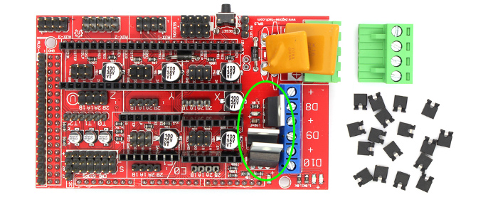
It features just 3 power outputs (two heads + fan, ignore the heated bed), all 3 outputs are very weak (18 mOhm), lack reverse protection diodes for inductive loads, MOSFET gates are driven directly by Arduino at 5V. Unable to pass more than 5-7A without heatsinks.
Geeetech GT2560 - exactly copies RAMPS, but has protection diodes implemented.
RAMBO, RUMBA - the same here. Weak 6.8 mOhm channels, gates driven by MCU, series 10 Ohm resistors in gate lines (literally blowing up the AVR MCU), lack of protection diodes. More channels however.
MKS Gen board is a little bit better here:
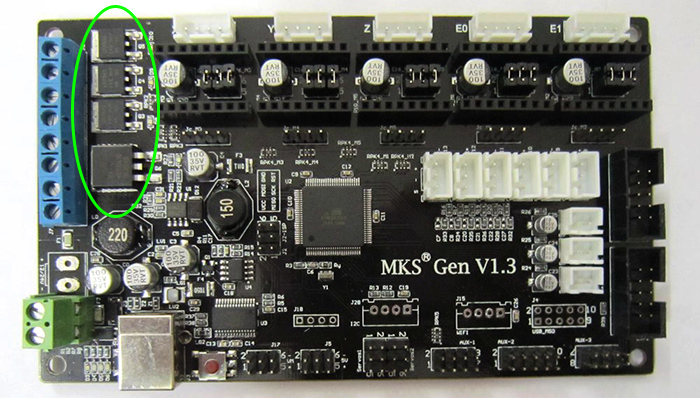
It utilizes 4 power outputs, but very strange ones.
Top three have good 3.3 mOhm FETS, but with Vds breakdown voltage of just 30V. Way too close to upper working voltage (24V). Lower, bigger FET handles bigger 60V, but has much higher Rds (18 mOhm, the same as installed in RAMPS board. No-go.
The board lacks reverse protection diodes (which is a real crime given MOSFET breakdown voltages are so close to nominal voltages, shame on chinese developers), gates are once again driven directly from MCU.
- External Solid-State relays (SSRs)
This is a common option if you want to extend the outputs or drive higher loads. Usually some devices made by FOTEK are used (and most commonly they are FOTEK fakes).
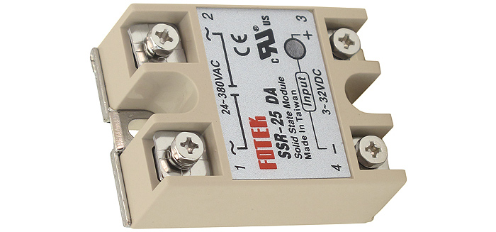
The problem here is that these SSRs (genuine too) are intended to drive AC loads, and are useless with DC loads. Even if one takes a 40A-rated SSR to drive a tiny 15A load, the SSR will melt in a minute. Heatsinks help here, but not too much.
Pros: isolated input/output, possible to install on "High" side, can drive AC loads. No other benefits to former solution.
- Electromagnetic relays
These devices are currently installed in our Cheap3D V300 3D printer.
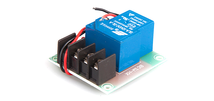
They are cheap, easy to find, can handle 30A, build moderate heat, have isolated inputs.
Cons: You can't directly drive them with Arduino logic-level pins, so have to use any of RAMPS power output, low frequency - can't drive with PWM by PID-regulator, and they are noisy by frequent clicking :(
Summary: Nobody ever bothered to solve this problem. Re-inventing this bicycle from scratch.
Features of our board:
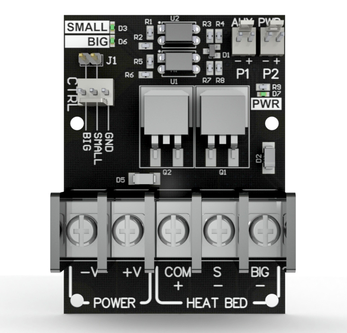
- Two power channels.
You can connect both zones of our two-zone heated bed.
Or you can pair both channels into a more powerful one with a single jumper, and drive even higher load.
Alternatively, you can connect the heated bed + extra extruder heater. Or drive CNC mill spindle motor.
So, it's possible to drive any high-current DC load.
- Powerful and expensive MOSFETs with Rds(on) of 1.4mOhm
Large current margin. Continuous current for each channel handled is 30A. Two channels (combined or both) - 60A. Two channels combined = 0.7mOhm
At these conditions, the board is virtually cold. No need for heatsinks, fans, etc stuff.
These MOSFETs can handle up to 100A each (in fact these are 180A beasts), but they would then require heatsinks and much more powerful screw terminals.
Voltage drop is extremely low (21mV at 15A+15A), so your heated bed would get to operational temps much faster.
- Opto-isolated inputs and outputs
Both channels are fed through optocouplers. No current flow between logic side and power side.
So, you can safely use a different PSU to drive your high loads.
I.e. you can power up your electronics with a weak 12V PSU and drive the heated bed with a separate 24V PSU
As a bonus, the MOSFET gate lines are no more driven with AVR MCU directly, so edges are much better. Also, due to higher gate drive voltages (12V regardless of supplied voltages), MOSFETs handle higher currents in avalanche mode, not falling into linear region.
- Reverse protection diodes.
Most 3D Printer electronics boards lack reverse diodes that are useful to protect MOSFETs from inductive load voltage spikes that can reach twice the supplied voltages and kill your MOSFETs some day. This board has a dedicated protection diode per each channel.
- Wide operating voltages
The board can work both with 12V or 24V out of the box.
Control logic side can be driven either directly from your Arduino 5V ports (or any other electronics as well) drawing minor 5mA - you can connect it to any AUX pins available, or, you can control it with your board's power outputs (up to 12V).
With some resoldering (change resistors) you can drive the logic side even with 24V, and changing optocouplers to more sensitive ones, you can hook it directly to 3.3V ARM MCUs.
- PWM-compatible.
You can now drive your heated bed with PWM PID-regulator. The board supports PWM frequencies up to 1KHz (projected. Can possibly be higher based on real-product evaluation). This is more than enough for your Marlin firmware.
- Extra features.
It's useful to have two extra sockets to power up some always-on hardware like hotend fans, LED backlight, etc. These get power directly from V+/V- terminals.
Board also carries three (very dim :) LEDs: one for "Power On", and two other for each channel.
If you install the J1 jumper in place, you can combine both channels and drive them all at once with one wire.
Barrier terminal blocks used are wide-available 9.5mm pitch and can handle up to 30А for each terminal continuously.
- It is Open Hardware!
To make more people use our board, we decided to release it under "Open hardware" license. That is, we would release all the BOMs, schematics, Gerber files online after we thoroughly test everything. The board is a simple 2-layer PCB, no exotic components, solderable by hand.
- Projected retail price ~$15-20 worldwide shipped.
Starting production. Developed and seriously made in Russia.
Comments, questions, early orders, offers & proposals - welcome to cheap3d@cheap3d.ru !:)


